Sequence flow documentation with PlantUML
Table of Contents
Motivation
After working and developing production systems I have realized the importance of documentation. Not that I didn't know that documentation was necessary but there is a difference between knowing and understanding. When you know something its just knowledge but when you understand, that knowledge becomes actionable. To that effect, this document details how to use PlantUML for creating diagrams as code for enriching software documentation.
Why PlantUML
There are plenty of tools for generating workflow documentation out there,
These tools are mostly web based and offer a rich feature set when creating workflows. I prefer PlantUML primarily because it allows creating workflow documentation as code with a "reasonably" clear syntax i.e. the code for the workflow can live within the project or service repository. Furthermore, it offers substantial preprocessing 1 primitives which enables expressing complex diagram generation and exporting scenarios.
PlantUML basics
Setup PlantUML
Download the plantuml.jar file from the PlantUML website. Now you can install
Java locally to run .jar file but I find GraalVM much more easy to setup and
fast to use for working with JVM ecosystem. When using Linux its quite easy to
setup with instructions shared here. After the setup is complete and you have
java available in your PATH and JAVA_HOME set we are ready to generate our
first diagram using PlantUML.
NOTE: Another convenient alias which I use to ease diagram generation is,
alias plantuml="java -jar /path/to/plantuml.jar"
Generate the first diagram
Save the code below in a file first-puml-diagram.pum and execute plantuml
first-puml-diagram.pum This will generate first-puml-diagram.png in your
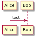
current directory and the result will look as follows,
@startuml
Alice -> Bob: test
@enduml
Styling PlantUML
PlantUML is quite flexible with its styling configuration for the generated
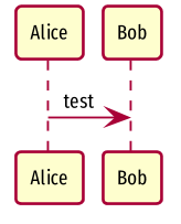
images. Some would say a bit too flexible. In order to style a PlantUML diagram
skinparam directive can be used,
@startuml
scale 150 width
skinparam {
	Shadowing false
	DefaultFontName Fira Sans Compressed
	RoundCorner 5
	TitleBorderRoundCorner 5
	DefaultFontSize 10
	Padding 0
}
Alice -> Bob: test
@enduml
The usage is quite similar to how a lay backend dev would write CSS! To list
all properties which can be styled, execute plantuml -language. And just like
one would separate out the stylesheet into independent file, herein it would be
a good practice to do the same and separate skinparam into it's own file
skinparam.pum.
Practical PlantUML
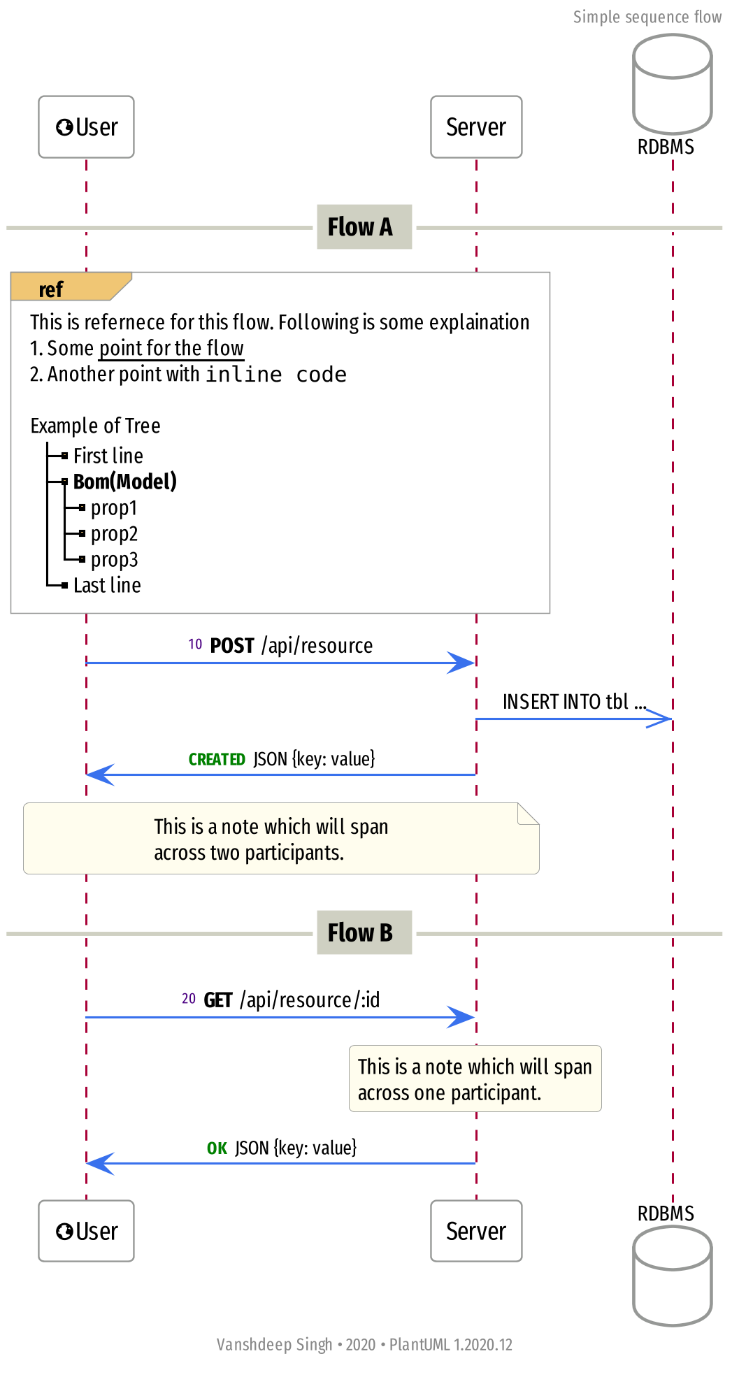
In order to understand how to use PlantUML to create practical diagrams we take an example API service whose flow shall be described via PlantUML. Below is how the final exported sequence flow generated using PlantUML. In the remaining sections we go over the various elements to understand how to generate such a sequence flow diagram and how to manage PlantUML code.
Sequence elements
The primary component of a sequence flow diagram are the participants.
@startuml
'PARTICIPANTS
participant "<&globe>User" as Client
participant Server
database RDBMS
internal_participant("3rd Party", "External")
@enduml
Notice database is a special kind of participant which would be the logical
way to represent storage in the flow. Another think to notice is
internal_participant() which will be discussed later. For more details
regarding participants refer the plantuml sequence flow docs.
Sequence interactions
Once the set of participants for a sequence diagram has been defined the
sequence flow can be described using these participants. The most basic set of
interaction seen previously is Alice -> Bob which creates a unidirectional
arrow originating from Alice and pointing to Bob.
- PlantUML Procedures
Based on the context of a sequence diagram is a good practice to define interactions as a set of procedures which can then be used to define the interactions between participants, following are the procedures defined the PlantUML diagram generated above (
definitions.pum),@startuml !procedure HTTP_REQUEST(source, destination, method, uri) autonumber resume source -> destination: <b>method</b> uri !endprocedure !procedure HTTP_REQUEST_INTERNAL(source, destination, method, uri) !if %variable_exists("INTERNAL") HTTP_REQUEST(source, destination, method, uri) !endif !endprocedure !procedure HTTP_RESPONSE(source, destination, code, payload) autonumber stop source -> destination: <font size=8 color=green><b>code</b></font> <size:9> payload !endprocedure !procedure HTTP_RESPONSE_INTERNAL(source, destination, code, payload) !if %variable_exists("INTERNAL") HTTP_RESPONSE(source, destination, code, payload) !endif !endprocedure !procedure DB_QUERY(source, destination, query) autonumber stop source ->> destination: query !endprocedure !procedure internal_participant(name, reference) !if %variable_exists("INTERNAL") participant "name" as reference !endif !endprocedure @enduml!procedure ... !endproceduredefines a procedure (i.e. macro) and herein we define the following procedures,HTTP_REQUEST,HTTP_RESPONSEHTTP_REQUEST_INTERNAL,HTTP_RESPONE_INTERNALDB_QUERYinternal_participant
Notice, the
!if %variable_exists("INTERNAL") ... !endifblock in procedures which haveINTERNALin their name. Thisifcondition skips the sequence interaction if a variable namedINTERNALis not defined. This allows to generate multiple PlantUML diagrams wherein some components and interactions are removed. This might be desirable based on the expected audience of the diagram.Following previously,
internal_participantis just another participant which is conditionally added to the exported diagram if theINTERNALvariable is set.
Skinparams
Skinparams allow styling of the generated PlantUML diagram. There are few a lot
of styling options available, following are the skinparams used for the
generated PlantUML diagram (skinparam.pum),
@startuml
scale 1024 width

skinparam {
	Shadowing false
	DefaultFontName Fira Sans Compressed
	RoundCorner 5
	TitleBorderRoundCorner 5
	DefaultFontSize 10
	Padding 0
}

skinparam Participant {
	FontSize 12
	BorderColor #969896
	BackgroundColor #ffffff
	Padding 10
}

skinparam Arrow {
	Color #3971ed
	MessageAlignment left
}

skinparam Sequence {
	MessageAlign center
	ParticipantBorderThickness 0.8
	DividerBorderThickness 2
	DividerBorderColor #fff
	DividerBackgroundColor #cfd0c2
	DividerFontSize 12
	ReferenceBorderThickness 0.5
	ReferenceBorderColor #969896
	ReferenceHeaderBackgroundColor #f0c674
}

skinparam Footer {
	FontSize 8
}

skinparam Header {
	FontSize 8
}

skinparam Database {
	BackgroundColor #fff
	BorderColor #969896
}

skinparam Note {
	BackgroundColor #fffdee
	BorderColor #969896
	BorderThickness 0.3
}

@enduml
Herein we define skinparam only for the components used in our diagram i.e.
Sequence elements, Arrow, Database etc. To get a list of all the
skinparams which can be configured use plantuml -language. Refer here for more
details regarding this topic.
Organizing PlantUML Code
As seen above sequence diagrams definitions can grow quite quickly so it is good practice to organize the plantuml code in a modular fashion to avoid "spaghetti" code. The most basic form of layout can be as following,
puml/
├── definitions.pum
├── sequenceDiagram.pum
└── skinparam.pum
A more complicated setup can be used in based on requirements and can involve `Makefile` to generate different diagram targets.
Final take
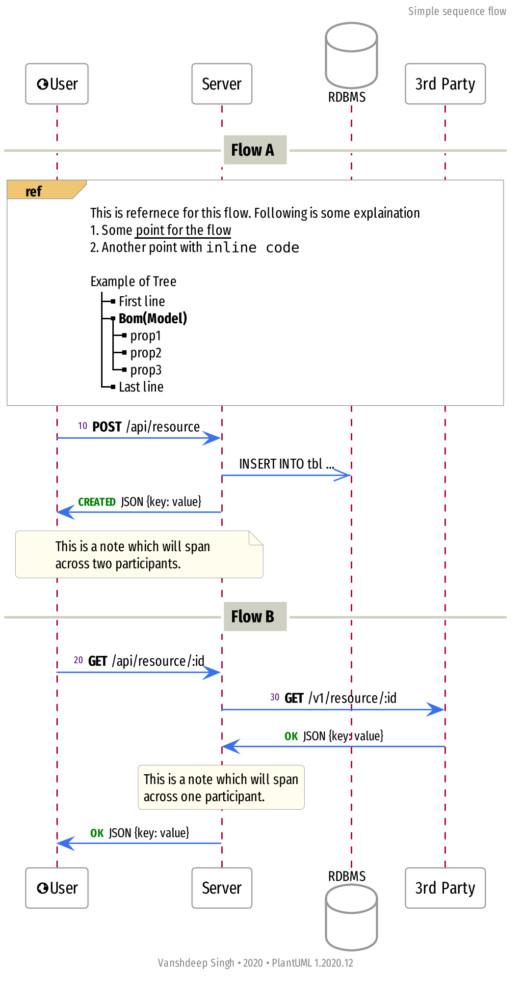
Once the above definitions and skinparams have been properly defined the
following sequenceDiagram.pum brings it all together,
@startuml
!include skinparam.pum
!include definitions.pum

header Simple sequence flow
center footer Vanshdeep Singh • 2020 • PlantUML %version()

!INTERNAL = %true

'PARTICIPANTS
participant "<&globe>User" as Client
participant Server
database RDBMS
internal_participant("3rd Party", "External")

'VARIABLES
!if %variable_exists("INTERNAL")
!SERVER = "Server"
!EXTERNAL = "External"
!else
!SERVER = "Server"
!EXTERNAL = "Server"
!endif

autonumber 10 10 "<font size=7 color=indigo>0"

/'
 ' DIAGRAM
 '/
== Flow A ==
ref over Client, EXTERNAL
	This is refernece for this flow. Following is some explaination
	# Some __point for the flow__
	# Another point with ""inline code""

	Example of Tree
	|_ First line
	|_ **Bom(Model)**
	  |_ prop1
	  |_ prop2
	  |_ prop3
	|_ Last line
end ref

HTTP_REQUEST("Client", SERVER, "POST", "/api/resource")
DB_QUERY(SERVER, "RDBMS", "INSERT INTO tbl ...")
HTTP_RESPONSE(SERVER, "Client", "CREATED", "JSON {key: value}")

note over Client, SERVER
	This is a note which will span
	across two participants.
end note

== Flow B ==
HTTP_REQUEST("Client", SERVER, "GET", "/api/resource/:id")
HTTP_REQUEST_INTERNAL(SERVER, EXTERNAL, "GET", "/v1/resource/:id")

HTTP_RESPONSE_INTERNAL(EXTERNAL, SERVER, "OK", "JSON {key: value}")

rnote over SERVER
	This is a note which will span
	across one participant.
end note

HTTP_RESPONSE(SERVER, "Client", "OK", "JSON {key: value}")

@enduml
Notice how we have !include directive is used to include the definitions and
skinparams. There are various other components that have used here to create
sections (== Flow A ==), notes etc 2 .
Disable components
The last outstanding item to discuss is enabling/disabling components of the
above PlantUML so that the sequence diagram can be tailored for its audience.
Notice in the above PlantUML definition a variable named INTERNAL is defined.
In the previous section we saw some procedures which check the existence of this
variable before adding components to the diagram. We can delete this variable
from the PlantUML definition and generate the sequence diagram which will
exclude any components which have been marked internal.